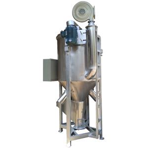
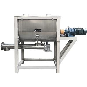
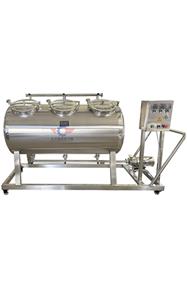
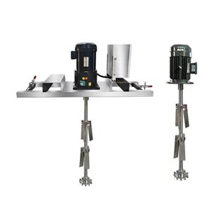
IBC Agitator Mixer Horizontal IBC Tank Mixer
A device that forces convection and uniform mixing of liquid and gas media. The type, size, and speed of the stirrer have an impact on the distribution of stirring power between overall flow and turbulent pulsation. Generally speaking, the power distribution of a turbine stirrer is beneficial for turbulent pulsation, while a propeller stirrer is beneficial for overall flow. For the same type of agitator, under the same power consumption conditions, large diameter and low speed agitators mainly consume power for overall flow, which is conducive to macroscopic mixing. A small diameter, high speed stirrer mainly consumes power due to turbulent pulsation, which is beneficial for micro mixing.
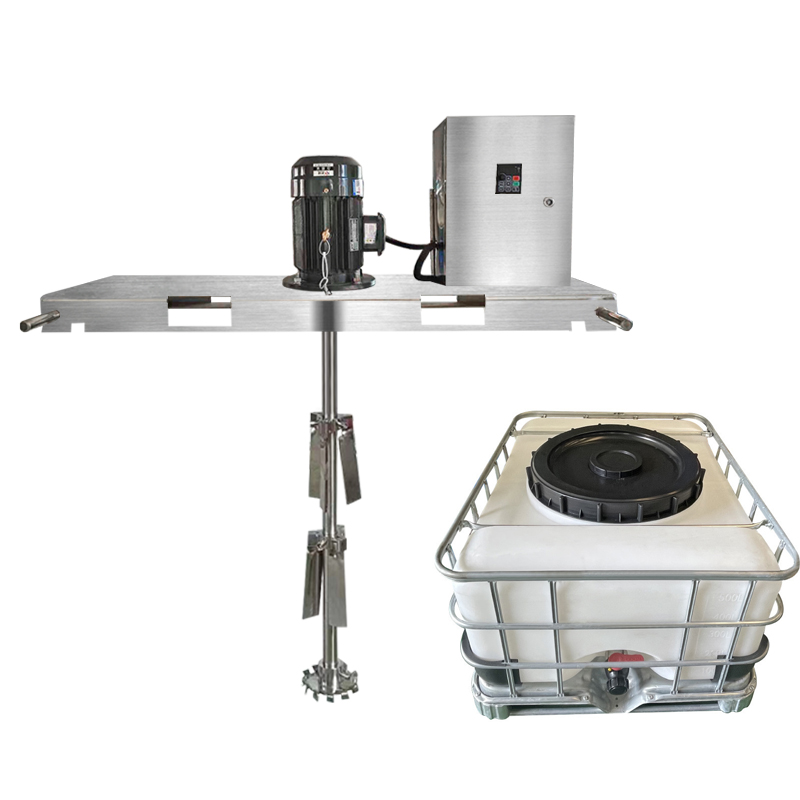
Analysis and Introduction of Mixer Selection Steps
The design and selection of mixing devices are closely combined with the purpose of mixing operations. Various mixing processes require different mixing devices to operate. In the design and selection process, the mixer type, motor power, and mixing speed should be determined based on the purpose and requirements of the process for the mixing operation. Then, various components such as the reducer, frame, mixing shaft, and shaft seal should be selected. The specific steps and methods are as follows:
According to the process conditions, mixing purpose, and requirements, choose the type of agitator. When selecting the type of agitator, it is necessary to fully grasp the dynamic characteristics of the agitator and the causal relationship between the flow state generated by the agitator during the mixing process and various mixing purposes.
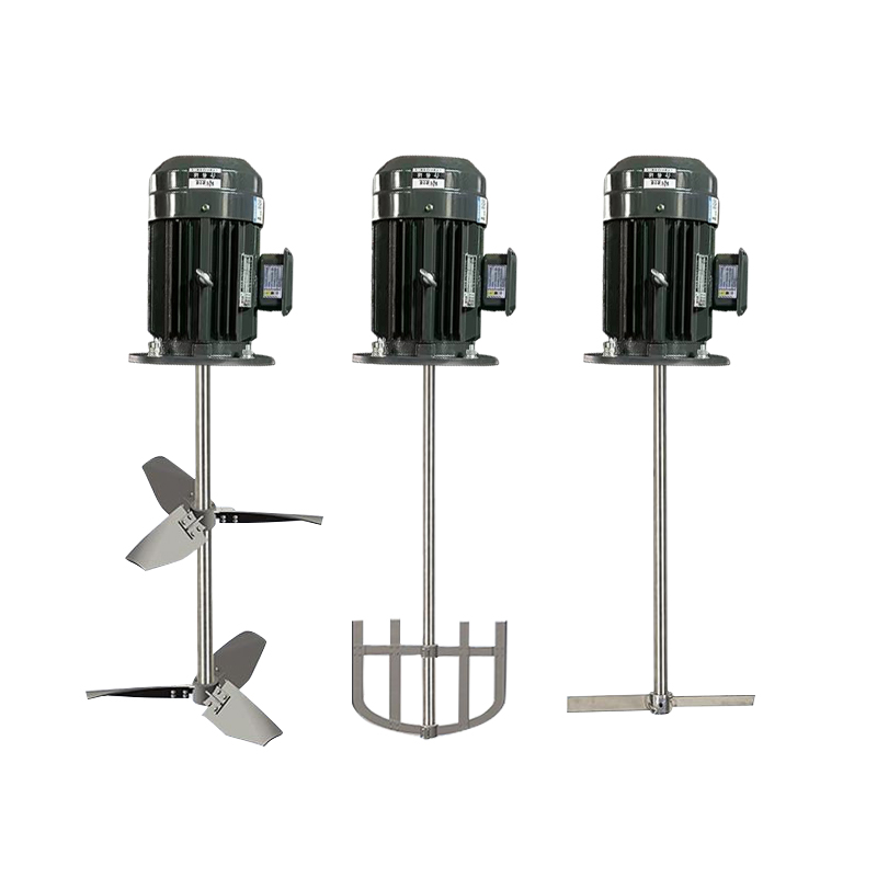
2. Determine the motor power, mixing speed and agitator diameter through experimental means and computer simulation design according to the determined agitator type, the flow state generated by the agitator in the mixing process, and the process control requirements for mixing time, settling speed and Dispersity.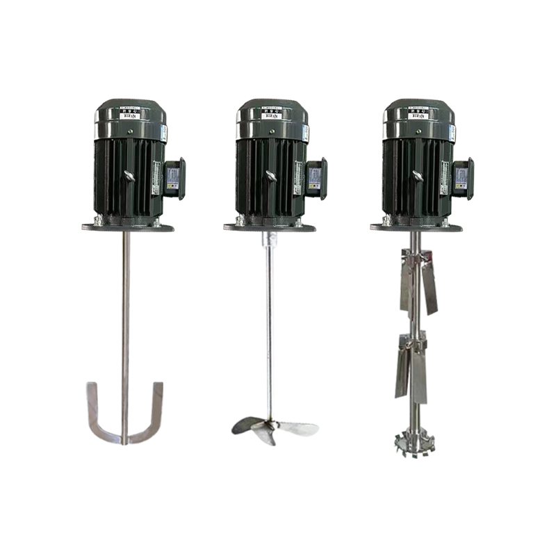
3. According to the motor power, mixing speed, and process conditions, select and determine the gearbox model from the gearbox selection table. If the reducer is selected based on the actual working torque, the actual working torque should be less than the allowable torque of the reducer.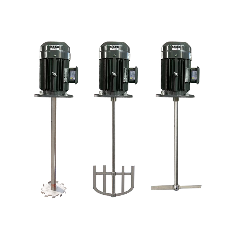
4. Select the same model and specifications of the frame and coupling as d according to the output shaft head d of the reducer and the support method of the mixing shaft system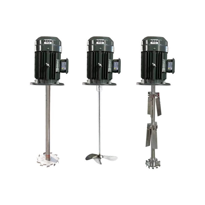
5. Select the shaft seal type according to the size, installation capacity, working pressure, and working temperature of the mixing shaft head of the rack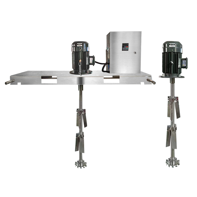
6. According to the installation form and structural requirements, design and select the mixing shaft structure type, and check its strength and stiffness.
If designed according to rigid axis, n/nk ≤ 0.7 under strength conditions
If designed according to the flexible shaft, n/nk>=1.3 when meeting the strength conditions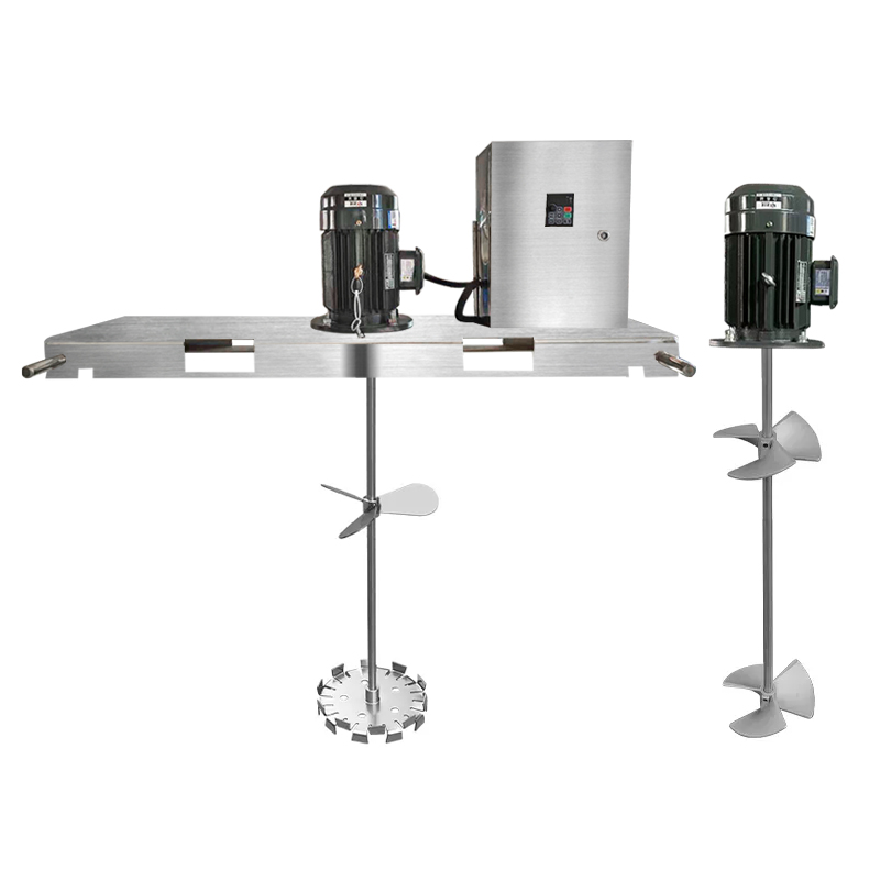
7. According to the nominal center size DN of the rack, the type and pressure rating of the mixing shaft, choose to install the bottom cover, flange base, or flange flange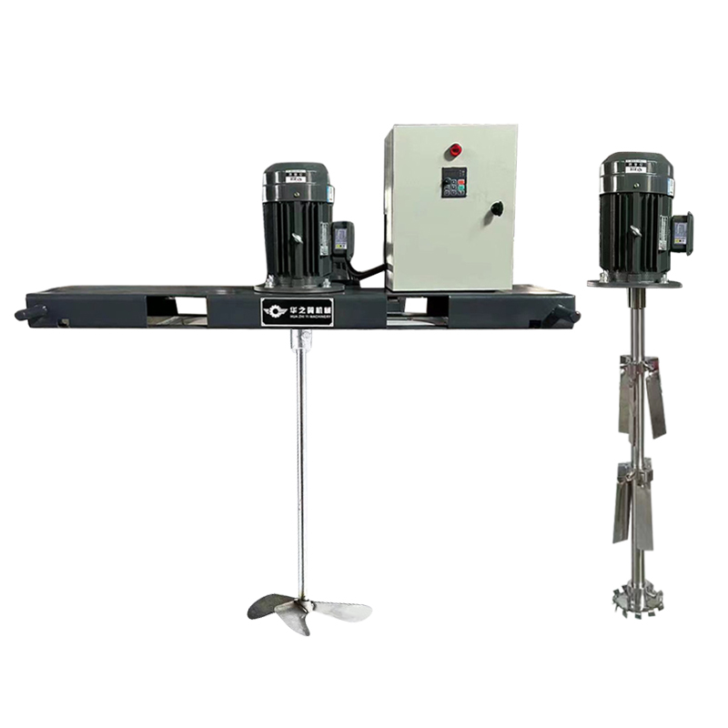
8. Determine whether to configure auxiliary supports based on the support and vibration resistance conditions.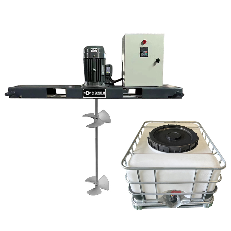
In the above selection process, the combination and configuration of the mixing device can be referred to (schematic diagram of the mixing device design selection process). The key dimension for connecting various components during the configuration process is the shaft head size. In principle, components with the same shaft head size can be interchanged and combined.
